Understanding the ESP32's LEDC Peripheral
The ESP32 microcontroller features a dedicated peripheral module known as LEDC, an acronym for 'LED Control' or 'LED PWM Controller'. This module is specifically designed to facilitate Pulse Width Modulation (PWM), a technique used to control the average voltage supplied to a device by rapidly switching it on and off. For applications like dimming LEDs, this rapid switching is too fast for the human eye to perceive, resulting in a smooth transition in brightness. While the name suggests LED control, the LEDC peripheral's capabilities extend to generating various waveforms beyond simple dimming.
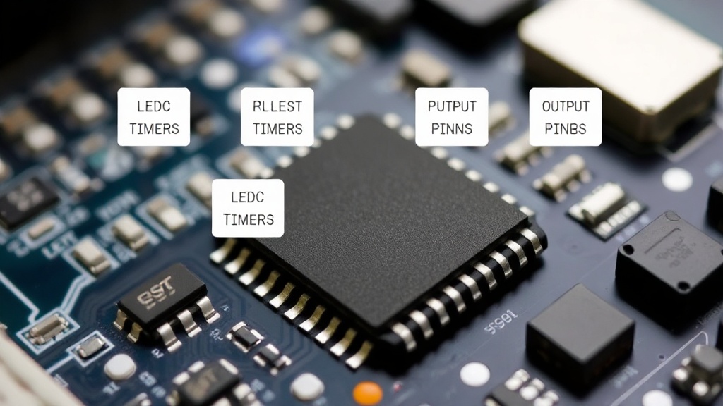
Most ESP32 variants are equipped with a single LEDC module. Internally, the original ESP32's LEDC architecture comprises four independent timers and sixteen distinct output channels. This architecture allows for simultaneous control of multiple PWM signals with varying frequencies and duty cycles, offering significant flexibility for complex projects.
Controlling the LEDC Module: Registers and Peripherals
The LEDC peripheral is managed by interacting directly with its internal registers. These registers are termed 'peripheral registers' because they are dedicated to the LEDC module and are distinct from the CPU's internal registers. Working with these registers allows for fine-grained control over the PWM signal generation. Each register is 32 bits wide, meaning each bit can be independently set to either 0 or 1, enabling precise configuration of the module's behavior.
The core of LEDC functionality lies in its timers and channels. The timers dictate the base frequency of the PWM signal, while the channels translate these timer configurations into specific output signals. Each channel can be independently configured to use one of the available timers, set its own duty cycle, and determine its output pin. This separation of concerns allows for flexible allocation of resources; for instance, one timer can drive multiple channels with the same frequency but different duty cycles.
LEDC Timers: The Heartbeat of PWM
The ESP32's LEDC module provides multiple timers, typically four on the original ESP32. These timers are crucial for defining the frequency of the PWM signals. A timer's configuration involves setting its resolution and its period. The resolution determines the number of distinct duty cycle levels available, while the period defines the duration of one full PWM cycle (the time from one rising edge to the next). A higher resolution allows for finer control over the duty cycle, enabling smoother dimming or more complex waveform shapes. The period, combined with the timer's clock source, sets the PWM frequency.
When a timer is configured, it generates a counter that increments. When this counter reaches a specific value (defined by the timer's period or compare values), it can trigger an event or reset. This timed event is what underpins the generation of the PWM signal. Developers must carefully select the timer resolution and period to match the requirements of their application, balancing the need for precision with the available processing power and the desired output frequency. For instance, driving a high-frequency servo motor will demand a different timer configuration than dimming a slow-fading LED.
LEDC Channels: Outputting the PWM Signal
Each of the sixteen LEDC channels acts as an independent output. A channel can be linked to one of the available timers. Once linked, the channel uses the timer's clock and period to generate its PWM signal. The key configurable parameter for each channel is its duty cycle. The duty cycle specifies the proportion of time the signal remains high within a single PWM period. For example, a 50% duty cycle means the signal is high for half the period and low for the other half.
The actual value written to the channel's duty cycle register determines this proportion. The maximum value of this register is dictated by the timer's resolution. If a timer has a resolution of 8 bits, its maximum counter value is 255. A duty cycle of 50% would then correspond to a value of approximately 128. If the resolution is 10 bits (maximum value 1023), 50% duty cycle would be around 512. This allows for a wide range of control, from fully off (0% duty cycle) to fully on (100% duty cycle), with many intermediate levels in between.
Furthermore, channels can be configured for different operational modes, including high-speed output, low-speed output, and even dead-time generation, which is crucial for applications like motor control to prevent short circuits. The ability to assign channels to specific GPIO pins on the ESP32 provides the flexibility to connect the PWM output to virtually any external component.
Practical Applications and Considerations
The LEDC peripheral on the ESP32 is incredibly versatile. Its primary use case, as the name suggests, is for dimming LEDs. By modulating the duty cycle, developers can achieve precise brightness control, essential for ambient lighting, status indicators, or even creating visual effects. Beyond LEDs, PWM is fundamental for controlling the speed of DC motors, which is often done by adjusting the voltage supplied to the motor via a PWM signal. This is a common requirement in robotics and automation projects.
Other applications include generating audio signals with simple DACs (Digital-to-Analog Converters) by filtering the PWM output, controlling the position of servos, and creating custom waveforms for testing or specific electronic circuits. The ESP32's ability to generate multiple independent PWM signals simultaneously makes it suitable for projects requiring simultaneous control of several actuators or indicators.
When working with the LEDC, developers need to consider the trade-offs between frequency, resolution, and the number of channels used. Increasing the resolution or frequency might consume more processing resources or lead to limitations in the number of channels that can be driven simultaneously at high speeds. Understanding the ESP32's datasheet and the specific configurations available for the LEDC peripheral is key to successful implementation. For instance, using lower resolution timers can free up resources for higher PWM frequencies or allow more channels to operate concurrently.
The LEDC peripheral is typically accessed through the ESP-IDF (Espressif IoT Development Framework) or other SDKs, which provide higher-level APIs that abstract away the direct register manipulation. These APIs simplify the process of configuring timers, channels, and duty cycles, making PWM generation more accessible to developers. However, for advanced use cases or performance-critical applications, understanding the underlying register-level control remains valuable.