
The Problem: Bridging Airfoil Data and CAD
Engineers and researchers working on aerodynamic analysis often encounter airfoil coordinate data in the ubiquitous .dat file format. These files, frequently sourced from databases like those for NACA airfoils (e.g., NACA 2412), contain precise two-dimensional coordinates defining the airfoil's shape. However, modern CAD (Computer-Aided Design) and CAE (Computer-Aided Engineering) software, essential for modeling, simulation, and manufacturing, typically require geometry in vector formats like .dxf (Drawing Exchange Format).
The gap between readily available .dat files and the import requirements of CAD software presented a significant hurdle. Existing online converters were often unreliable, lacked necessary customization, or produced output unsuitable for direct import into professional design tools. This lack of a clean, dependable conversion pathway hindered projects requiring detailed airfoil modeling, such as the comparative aerodynamic analysis of wing planforms.
Spondon Saha, a developer and researcher, faced this exact challenge while working on a project involving the aerodynamic analysis of wing planforms. His specific need was to model a NACA 2412 wing using .dat coordinate files, but his chosen CAD platform, Onshape, required .dxf files for geometry import.
The Solution: A Custom Python Converter
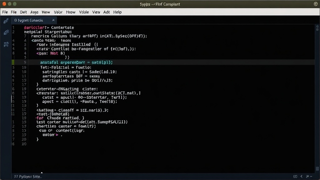
Unable to find a satisfactory solution, Saha took a developer-centric approach: he built his own converter. The solution is a Python script designed to parse .dat files containing airfoil coordinates and generate a corresponding .dxf file. This script is part of a larger project, Comparative Aerodynamic Analysis Of Wing Planforms, highlighting its practical application.
The script, named plot_airfoil.py, is straightforward and focuses on the core task of geometric conversion. It imports necessary libraries for handling file operations and generating the DXF output. A key parameter is the desired chord length, specified in millimeters (CHORD = 200 in the example). This allows users to scale the imported airfoil to their desired physical dimensions within the CAD environment.
The conversion process involves reading the coordinate pairs from the .dat file. These points define the upper and lower surfaces of the airfoil. The script then translates these points into the specific entities and structures required by the DXF format. DXF files can represent various graphical entities, including lines, arcs, and polylines. For airfoil shapes, a polyline is a common and effective representation, connecting the discrete coordinate points to form a continuous outline.
The script's design prioritizes simplicity and direct functionality. It aims to provide a clean output that can be readily imported into CAD software without extensive post-processing. This is crucial for engineers who need to quickly integrate airfoil geometries into larger assemblies or simulation models. By making the script publicly available, Saha addresses a common pain point for a niche but important community within the aerospace and engineering fields.
Technical Details and DXF Structure
The .dxf format, developed by Autodesk, is a standard for interchanging CAD data. It is essentially a text-based file format that describes graphical entities, their properties, and their spatial relationships. A typical .dxf file is structured into sections, including HEADER, CLASSES, TABLES, BLOCKS, ENTITIES, and OBJECTS.
For an airfoil shape, the most critical section is ENTITIES. This is where the geometric data is defined. The script would likely define the airfoil's outline as a single LWPOLYLINE (Lightweight Polyline) entity. This entity is efficient and suitable for representing connected line segments that form a closed or open shape.
The coordinates read from the .dat file are mapped to the vertices of this polyline. The script needs to handle the order of points correctly, ensuring that the upper and lower surfaces are defined in a continuous path, typically starting from the trailing edge, proceeding to the leading edge along the upper surface, and then returning to the trailing edge along the lower surface to form a closed loop.
The script also needs to manage the scaling factor (the CHORD variable) to ensure the generated .dxf geometry reflects the intended physical dimensions. This scaling is applied to the raw coordinate data before it is written into the DXF structure. Units within DXF are generally unitless, meaning the interpretation of scale is left to the importing CAD software, but consistency in applying the chord length is vital for the user's workflow.
While the provided excerpt shows only the beginning of the Python script, the core logic would involve file reading, coordinate parsing, scaling, and then writing the DXF entity data according to the DXF file specification. Libraries like ezdxf in Python are commonly used for programmatic DXF creation, handling the complexities of the file format and allowing developers to focus on the geometry.
Implications for Aerodynamic Design and Research
The availability of a reliable .dat to .dxf converter has immediate practical benefits for several groups:
- Aerospace Engineers: They can now more easily integrate NACA and other standard airfoil profiles into their CAD models for aircraft design, wing optimization, and structural analysis.
- CFD Analysts: While CFD often uses specialized mesh formats, initial geometry definition in CAD is a common first step. A clean DXF import simplifies the creation of 2D cross-sections or 3D wing geometries that can then be meshed for simulation.
- Students and Researchers: Projects involving airfoil studies, wind tunnel model design, or comparative aerodynamic analysis, like Saha's own project, become more accessible. They can leverage existing airfoil databases without being blocked by format incompatibilities.
- Hobbyists and Makers: Individuals building RC aircraft, drones, or other aerodynamic devices can more readily incorporate precise airfoil shapes into their designs for 3D printing or CNC machining.
The surprising detail here is not the existence of airfoil databases, which are well-established, but the persistent lack of robust, user-friendly conversion tools for a common workflow. Saha's initiative fills this gap, demonstrating how a specific project requirement can lead to a broadly useful utility.
What remains to be seen is whether this script will evolve into a more comprehensive tool, perhaps supporting a wider range of airfoil file formats or offering more advanced DXF export options, such as layer management or entity grouping. For now, it serves as a critical enabler for anyone needing to translate classic airfoil data into a modern design environment.