
A Novel Framework for 2.5D System Design
Designing advanced semiconductor systems, particularly those employing a 2.5D integration strategy, presents significant challenges. This approach, which involves placing multiple chiplets (smaller, specialized dies) onto a single interposer substrate, offers a path to higher performance and greater design flexibility compared to monolithic System-on-Chips (SoCs). However, the intricate interplay between the placement of these chiplets and the size and routing complexity of the interposer substrate is critical for overall system efficiency. Traditional design flows often tackle these aspects sequentially, leading to suboptimal results and a circular dependency where the ideal interposer footprint depends on the chiplet placement, and vice-versa.
Researchers at the Agency for Science, Technology and Research (A*STAR) in Singapore have introduced a new technical paper detailing a framework designed to break this cycle. Titled “FAPlace: Joint Optimization of Chiplet Placement and Interposer Footprint for 2.5D Systems,” their work proposes a novel approach that simultaneously considers both chiplet placement and interposer footprint optimization. This integrated methodology aims to achieve a more efficient and effective design process for complex 2.5D systems.
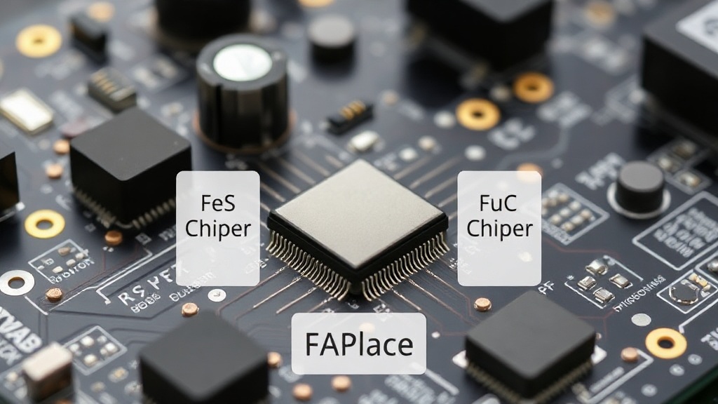
The FAPlace Framework Explained
At its core, FAPlace is a footprint-aware, mask-guided sequential placement framework. The key innovation lies in its ability to operate on a sufficiently large, predefined canvas. This eliminates the iterative dependency that plagues conventional methods. Instead of pre-determining an interposer size and then trying to fit chiplets, FAPlace allows the optimal interposer footprint to emerge as a result of the chiplet placement process itself. This means the framework can explore a wider design space, potentially uncovering more efficient configurations that might be missed by rigid, pre-allocated interposer dimensions.
The framework operates by first defining a large bounding box, or canvas, that encompasses the potential area for all chiplets and their associated interconnections. Within this canvas, FAPlace then proceeds with a sequential placement strategy. This strategy is guided by masks, which are essentially templates or rules that dictate how chiplets can be positioned and interconnected. These masks help to manage the complexity of routing signals between chiplets and from the chiplets to the package substrate, ensuring that critical design constraints are met.
By allowing the interposer footprint to be determined dynamically, FAPlace can significantly reduce the wasted area on the interposer. In 2.5D integration, the interposer is a critical and often costly component. Minimizing its size while still accommodating all necessary connections directly translates to reduced manufacturing costs and potentially improved signal integrity due to shorter trace lengths. The sequential nature of the placement, combined with the mask guidance, ensures that the process remains manageable and produces placement solutions that are manufacturable within the constraints of modern semiconductor fabrication processes.
Addressing the Challenges of 2.5D Integration
The rise of chiplets is a fundamental shift in semiconductor design. Instead of building ever-larger, monolithic chips that become increasingly difficult and expensive to manufacture with high yields, designers are opting to partition functionality into smaller, specialized chiplets. These chiplets can be manufactured using different process nodes, allowing for cost optimization and the integration of cutting-edge technologies where they are most needed. 2.5D integration, with its interposer substrate, is a key enabler of this chiplet revolution, providing the high-bandwidth interconnectivity required for these disparate dies to function as a cohesive system.
However, the interposer itself is a complex component. It requires advanced manufacturing techniques, such as silicon interposers with through-silicon vias (TSVs) or organic interposers with micro-vias. The routing density on these interposers can be extremely high, and the cost of the interposer can represent a substantial portion of the total package cost. Therefore, any method that can optimize the interposer footprint while ensuring all functional and electrical requirements are met is of significant value.
FAPlace directly addresses this by treating the interposer footprint not as a fixed constraint but as an emergent property of the placement algorithm. This allows for a more holistic optimization. For instance, if a particular chiplet placement pattern leads to concentrated routing needs in a specific area, FAPlace can adjust the interposer boundary to snugly fit these requirements, rather than forcing a larger, more uniform interposer that accommodates the worst-case scenario across the entire design.
Potential Impact and Future Directions
The implications of FAPlace are far-reaching for the semiconductor industry. For chiplet designers and system integrators, it offers a more efficient and potentially more cost-effective design flow for 2.5D systems. By reducing interposer size, manufacturers can lower material costs and potentially improve thermal performance due to reduced substrate mass. Furthermore, shorter interconnections enabled by optimized placement can lead to improved signal speeds and reduced power consumption, critical factors in high-performance computing, AI accelerators, and advanced networking applications.
The framework's success hinges on its ability to balance competing objectives: minimizing interposer area, ensuring routability, meeting performance targets (like signal latency and bandwidth), and maintaining manufacturability. The paper suggests that FAPlace's mask-guided sequential approach provides a robust mechanism for managing this complexity. Future work could involve further refining the mask generation process, exploring different sequential placement algorithms within the FAPlace framework, and validating its performance against a wider range of complex chiplet architectures and industry-standard design tools.
What remains to be seen is how readily this framework can be integrated into existing Electronic Design Automation (EDA) toolchains. For FAPlace to achieve widespread adoption, seamless integration with popular placement and routing tools, as well as verification flows, will be crucial. The success of such an optimization framework ultimately depends on its practical utility and ease of use for design engineers working under tight development schedules.